European Medium Voltage Power Cable: N2XSEY 3 x ... 6/10 kV
XLPE Insulated, Copper Conductor, PVC Jacket
Sealcon, Inc, European & Domestic cable
European Part-No.
Description,
No. Cond. x cross-sec. mm2 & Nominal
Voltage
Insulation
Thickness mm
Shield
Cross-sec. mm2
Jacket
Thickness mm
Outer
Dia.
Copper
Weight
kg/km
Weight
ca. kg/km
AWG
34339
N2XSEY
3X25 6/10kV rm/16
3.4
16.0
2.5
43.0
1046.0
2850.0
4
34340
N2XSEY 3X35 6/10kV
rm/16
3.4
16.0
2.5
48.0
1210.0
3300.0
2
34341
N2XSEY 3X50 6/10kV
rm/16
3.4
16.0
2.5
50.0
1670.0
3750.0
1
34342
N2XSEY 3X70 6/10kV
rm/16
3.4
16.0
2.6
54.0
2250.0
4650.0
2/0
34343
N2XSEY 3X95 6/10kV
rm/16
3.4
16.0
2.8
58.0
2995.0
5700.0
3/0
34344
N2XSEY 3X120 6/10kV
rm/16
3.4
16.0
2.9
61.0
3715.0
6700.0
4/0
34345
N2XSEY
3X150 6/10kV rm/25
3.4
25.0
3.0
65.0
4635.0
7900.0
300
kcmil
34346
N2XSEY 3X185 6/10kV
rm/25
3.4
25.0
3.1
68.0
5645.0
9200.0
350
kcmil
34347
N2XSEY
3X240 6/10kV rm/25
3.4
25.0
3.3
74.0
7274.0
11450.0
500
kcmil
34348
N2XSEY 3X300 6/10kV
rm/25
3.4
25.0
3.3
79.0
9160.0
14450.0
600
kcmil
Power Rating & Electrical
Characteristics
Cross-sec.
in mm2
Power
Ratings
Conductor
Resistance +20°C/+68°F Ohm/km
Operating
Capacity µF/km
Effective
Resistance +90°C/+194°F Ohm/km
Inductance
per Conductor mH/km
Underground
Installation
Outdoor
Installation
3
x 25 rm/16
151
147
0.727
0.203
0.928
0.399
3 x 35 rm/16
181
178
0.524
0.225
0.669
0.378
3 x 50 rm/16
213
213
0.387
0.249
0.494
0.359
3 x 70 rm/16
261
265
0.268
0.283
0.343
0.338
3 x 95 rm/16
312
322
0.193
0.315
0.247
0.323
3 x 120 rm/16
355
370
0.153
0.345
0.197
0.311
3
x 150 rm/25
399
420
0.124
0.374
0.160
0.302
3 x 185 rm/25
451
481
0.0991
0.406
0.129
0.293
3
x 240 rm/25
523
566
0.0754
0.456
0.0991
0.282
3 x 300 rm/25
590
648
0.0601
0.495
0.0803
0.274
Technical
Data
European
Three conductor XLPE-insulated
power cables to VDE 0276
and IEC 60502
Temperature Range During installation
up to -5°C/+23°F
Operating Temperature Max. +90°C/194°F
Short Circuit Temperature Conductor +250°C/482°F
Shield +350°C/+662°F (duration)
(Short circuit duration up
to 5 sec.)
Nominal Voltages U0/U
6/10 kV
Operating Voltages Max. 12 kV
Test Voltages 15
kV
Test Voltages d.c. 48
kV
Power Rating To DIN VDE 0298
part 2
Minimum Bnding
Radius During installation
15x cable Ø
Tests According to
DIN VDE 0276 und IEC 60502
Code-Designation for
Power Cables with PVC or XLPE Insulation
Design
Identification
of Design
Explanations
Conductor
N
According
to VDE Standard
(No abbreviation for copper conductor)
A
Aluminum conductors
Y
Insulation of thermoplastic
Polyvinyl chloride (PVC)
2X
Insulation cross-linked
Polyethylene (XLPE)
Concentric
Conductor, Shielding
C
Concentric
conductors of copper wires and copper tape,
helically wounded
CW
Concentric conductors
of copper wires in wave conal formation
and and copper tape, helically wounded
CE
Concentric conductors
of copper wires and copper tape over each
individual conductor, helically wounded
Shielding
S
Shielding of copper wires
and copper tape, helically wounded
SE
Shielding of copper wires
and copper tape over each individual conductor,
helically wounded
(F)
Longitudinally water-proof
shielding
Armor
B
Armor of steel tape
F
Armor of galvanized flat
steel wires
G
Counter helix of galvanized
steel tape
Jacket
K
Lead jacket
Outer
Jacket
Y
PVC jacket
2Y
PE jacket
Cable
for U0/U 0.6/1 kV are
additionally designated with
-J
Cables with green-yellow
(green-natural) conductor are marked with
protective conductor
-O
Cables without green-yellow
(green-natural) conductor are marked without
protective conductor
Approvals
Cable
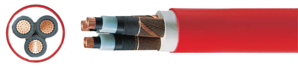
Construction
Circular bare copper conductor of
stranded wires to DIN VDE 0295
cl. 2 and IEC 60228 cl. 2
Inner semi-conducting coating
Conductor insulation of cross-linked
Polyethylene (XLPE), PE-compound
DIX8 to HD 620.1
Outer extrusion of semi-conducting
coating spliced with the XLPE-insulation
Conductive wrapping
Shield: Braiding of copper wires
with one or two tapes applied helically
3 conductors stranded
Extruded jacket over three conductors
PVC outer jacket, compound DMV6
to HD 405.1 and HD 620/1
Jacket color: Red
Application
Suitable
for indoor installation and
in cable ducts, outdoors,
underground and in water
as well as for laying racks
for industrial and switching
systems and power plants.
Limited use when buried in
ground if the PVC outer jacket
could be damaged by high
mechanical stress.
The inner conducting layer
between the conductor and the
XLPE insulation and the firmly
bonded outer conducting layer
on the XLPE insulation assures
a construction free of partial
discharges with high operational
reliability.
Properties
Self-extinguishing and flame
retardant according to DIN VDE
0482 part 265-2-1 / EN 50265-2-1 / IEC 60332-1 (equivalent DIN VDE
0472 part 804 test method B)
The materials used in manufacture
are cadmium-free, contain
no silicone and are free from substances
harmful to the wetting properties
of lacquers
Installation Notes To guarantee an optimum
on operating reliability the extruded
semi-conductive layer is spliced
with the insulation for long duration.
For this reason, we recommend a
peeling tool for installation.
Note
AWG sizes are approximate equivalent
values. The actual cross-section
is in mm².
For laying underground :
For ground thermal resistance of
1 K·m/W,
laying depth 0.7 m, ground temperature
+20°C/68°F, EVU load grade 0.7.
For laying outdoors : Air
temperature +30°C/+86°F, EVU load grade
1.0.
Conversion factors for laying in
ground especially for laying in bundle
form and other requirements are noted
din DIN VDE 0298 part 2 and 0276
part 1000.
Conversion factors for outdoor
installation
Air temperature/Conversion factor
15°C/1.12; 20°C/1.08; 25°C/1.04;
30°C/1.0; 35°C/0.96; 35°C/0.96;
40°C/0.91; 45°C/0.87; 50°C/0.82;
is the Exclusive Importer of HUMMEL products. We offer over 6,000 different Types and Sizes of RoHS Compliant Liquid Tight Strain Relief Fittings, Cord Grips, Cable Glands, Circular Connectors, Conduit System, Industrial Enclosures and Other Related Cable Management Products which are rated the best in the industry.
7374 S. Eagle Street
Centennial, CO 80112-4221 USA
Toll Free: 800-456-9012 / 303-699-1135 FAX: 303-680-5344