|
| Since about 1970,
the cross-linked Polyethylene (XLPE) -insulated
power cables have been used in Germany. This
insulation possesses very good electrical, mechanical
and thermal characteristics in medium voltage
networks. This type of insulation has excellent
chemical resistance and is also resistant to
cold temperatures. Due to various advantages,
the XLPE-insulated type has vastly displaced
the traditional classic paper-insulated types
in many sectors. |
 |
In order to prevent
the penetration of moisture and also to extend
the duration of life, the XLPE insulated medium
voltage cables are designed with longitudinally
waterproof shielding including an additional
swell tape and PE outer jacket.
The manufacture of this jacket is based on high
density polyethylene (HDPE), in which an additive
organic peroxide is mixed. Due to the heating
and pressure the molecule chains are joined together,
assuring the transition from thermo plastic to
elastic condition.
In comparison to PVC and paper-insulated cables,
the advantage of XLPE-insulated medium voltage
power cables is that they possess a low
dielectric factor, such as it is 100 times smaller
than of PVC-insulated cables.
Moreover, a better dielectric constant value
has has an effect on the low mutual capacitance,
the short circuit to ground and the charging
current of XLPE-insulated cables.
The good properties of these cables remain constant
at a wide temperature range. |
|
|
| Permissible
operating temperature: |
| |
| For permanent
(normal) operation: |
+ 90°C/+194°F |
| In short circuit: |
+250°C/+482°F |
| In overload operation
and damage by sea: |
up to +130°C/266° F |
|
| Specific
heat resistance: |
3.5 K x m/W |
| Dielectric constant: |
2.4 |
| Specific resistance
(20°C): |
min. 1016 Ohm
x cm |
| Loss factor (tan δ)
(20°C): |
max. 0.5 x 10⁻³ |
| Density: |
0.92 g/cm3 |
| Breaking strength: |
min. 200% |
| Tensile strength: |
min. 12.5 N/mm2 |
|
|
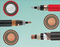
Conductor & Inner
Semi-Conducting Layer
|
|
|
Conductor
- Copper or Aluminum, round, multi-wire
stranded and compact, according to VDE
0295 and HD 383.
Inner Semi-Conducting Layer
- Semi-conducting compound, cross-linked,
min. wall thickness 0.3 mm.
|
|
|
- Cross-linked Polyethylene
(XLPE), compound type 2XI1 according to DIN
VDE 0207 part 22 an HD 620.1
- Insulation nominal wall thickness
| 6/10
kV |
= |
3.4
mm |
| 12/20
kV |
= |
5.5
mm |
| 18/30
kV |
= |
8.0
mm |
|
|
Outer
Semi-Conducting Layer
|
|
- Outer semi-conducting layer is
extruded together with the inner
semi-conducting layer and the insulation
in one working process and are spliced
with each other
- Semi-conducting compound, cross-linked,
wall thickness 0.3 to 0.6 mm
|
|
|
Concentricity
of Conductor
|
|
|
- The difference between the maximum and
minimum value of 0.5 mm should not be exceeded.
|
|
|
- Over the outer semi-conducting layer, a
semi-conducting tape must be used.
|
|
|
- Shielding of copper wires must have a minimum
diameter of 0.5 mm and over that a copper
tape applied helically with a minimum thickness
of 0.1 mm.
- Copper cross-section according to DIN VDE
0273 and 0276.
|
|
|
- Over the shielding as well as under the
outer jacket a separating layer must be used
(e.g. tape).
|
|
|
- PE compound DMP2 according to HD 620.1
and 2YM3 to DIN VDE 0276 part 3, black, or
- PVC compound DMV6 according to HD 620.1 and
YM5 to DIN VDE 0207 part 5, red
- Wall thickness = 2.5 mm, for 1 x 500 mm2 /
30 kV = 2.6 mm
|
|
|
In order to avoid any damage,
the XLPE insulated medium voltage power cables
should be carefully laid and installed. It
must be ensured that the cables should not
be pulled over hard or sharp edges. The cable
ends must be sealed water-tight. After cutting
the length both ends must be sealed immediately.
An installation depth of 60 to 80 cm is recommended.
Single conductor cables are normally arranged
in a trefoil touching or triangular shape.
For installation in conduits, especially the
influence of thermal insulation of air space
between the cable and the inner wall of the conduit
should be considered. The inner diameter of the
conduit should be at least 1.5 times that of
the diameter of the cable. |
|
|
During the installation
of XLPE cables, the bending radius should not
be below the following values:
| Cable without
metal jacket |
= |
15
x cable Ø |
| Cable with
aluminum-laminated jacket |
= |
30 x
cable Ø |
|
|
|
During the installation,
the temperature should not be below the following
values:
| For XLPE
insulation + PVC jacket |
= |
- 5°C |
| For XLPE
insulation + PE jacket |
= |
-20°C |
|
|
Max.
Permissible Tensile Strength
|
|
|
By pulling the conductors
with a pulling head (not for armored cables)
P = No. of conductors x conductor cross-section
x δ
δ = permissible pulling tension N/mm2
| - for copper conductor: |
50 N/mm2 |
| - for aluminum conductor: |
30 N/mm2 |
|
|
Current
Carrying Capacity
|
|
|
According to VDE 0276 part
620, -5C or HD 620 S1 |
|
|
| Laying depth: |
0.7 - 0.8 m |
| Ground temperature in
laying depth: |
+20°C/+68°F |
| Specific heat resistance: |
1.0 K m/W |
| Load factor: |
0.7 (EVU-load) |
|
|
|
| Air temperature: |
+30°C/86°F |
| Load factor (permanent
load): |
1.0 |
|
|
|
Cables for conduit system
installation in ground, a reduction of the
current carrying capacity with a factor of
0.85 is recommended. |
|
|
| Kind of Voltage
Test |
Voltage
Test in kV |
| U0/U
= 6/10 kV |
U0/U
= 12/20 kV |
U0/U
= 18/30 kV |
| Voltage Test a.c. in
kV |
15 |
30 |
45 |
| Voltage Test d.c. in
kV |
48 |
96 |
144 |
| Voltage Test a.c. (1000
h) |
18 |
36 |
54 |
|
|
Voltage
Test of Cable System
|
|
|
During the operation or
after installing the medium voltage power cables,
the dielectric can be tested with alternating
or direct current. The test duration continues
30 minutes.
| Kind of Voltage Test |
U0/U
= 6/10 kV |
U0/U
= 12/20 kV |
U0/U
= 18/30 kV |
| Voltage Test a.c. in
kV |
12 |
24 |
36 |
| Voltage Test d.c. in
kV |
34
up to 48 |
67
up to 96 |
76
up to 108 |
|
|