Manual isolation valves allow for depressurization of
the pneumatic system so that system components
may be serviced safely. The system is depressurized
with the de-activation of the valve.
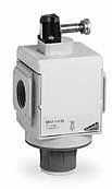
Electropneumatic isolation valves are ideal where
manual access is difficult since they allow maximum
positioning flexibility and are designed to pressurize
or depressurize pneumatic systems. The built-in
manual override guarantees security in case of an
emergency.
The Series MX has been realized to offer a multi-sector
solution that guarantees saving in terms of installation
time, space and costs.
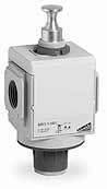
Shut-off valves with manual,
solenoid or air-pilot operation
8mm (0.315") OD hole for the lockout
feature accommodates most locks
and hasps (manual valve version)
Electro-pneumatic versions available
in 24 V, 110 V or 230 V
Quick-exhaust feature via port in base
Silencers available on request, 3/4" port
in base of valves for silencer assembly
Lockable (Lock-Out), manual valves Series MX
Part Number
A
B
C
D
F
G
I
N
O
P
Q
R
S
T
U
MX-3/4-V01TF
3/4
3/4
3.524
0.906
M30x1.5
1.969
2.992
8.091
1.437
2.618
1.063
4.035
3.720
1.752
0-0.25
MX3-1-V01TF
1
3/4
3.524
0.906
M30x1.5
1.969
2.992
8.091
1.437
2.618
1.063
4.035
3.720
1.752
0-0.25
Solenoid Pilot, Externally Piloted Solenoid or Air-Pilot valves
Part Number
A
B
C
D
G
I
N
N1
O
P
R
S
T
X
Y
MX3-3/4-V16TF
3/4
3/4
3.524
1.220
1.890
2.992
7.106
-
1.457
1.634
4.016
3.720
1.752
-
-
MX3-1-V16TF
1
3/4
3.524
1.220
1.890
2.992
7.106
-
1.457
1.634
4.016
3.720
1.752
-
-
MX3-3/4-V17TF
3/4
3/4
3.524
1.220
1.890
2.992
7.106
-
1.457
1.634
4.016
3.720
1.752
M5
-
MX3-1-V17TF
1
3/4
3.524
1.220
1.890
2.992
7.106
-
1.457
1.634
4.016
3.720
1.752
M5
-
MX3-3/4-V36TF
3/4
3/4
3.524
1.220
1.890
2.992
-
6.457
1.457
1.004
4.016
3.720
1.752
-
1/8
MX3-1-V36TF
1
3/4
3.524
1.220
1.890
2.992
-
6.457
1.457
1.004
4.016
3.720
1.752
-
1/8
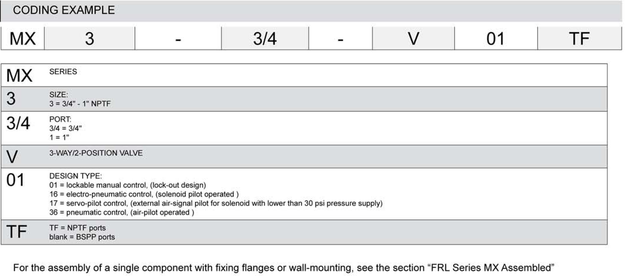
Coding Example & Flow Diagrams
(Click Image to Enlarge)
Coding Example
MX
3
3/4
V
01
TF
MX
Series
3
Size
3 = 3/4" - 1" body size
3/4
Ports 3/4 = 3/4" 1 = 1"
V
3-way/2-position valve
01
Design Type 01 = lockable manual control (lock-out design) 16 = electro-pneumatic control (solenoid pilot operated) 17 = servo-pilot control (external air-signal pilot for solenoid with lower than 30 psi pressure supply) 36 = pneumatic control (air-pilot operated)
TF
Port TF = NPTF Blank = BSPP thread ports
(Click Image to Enlarge)
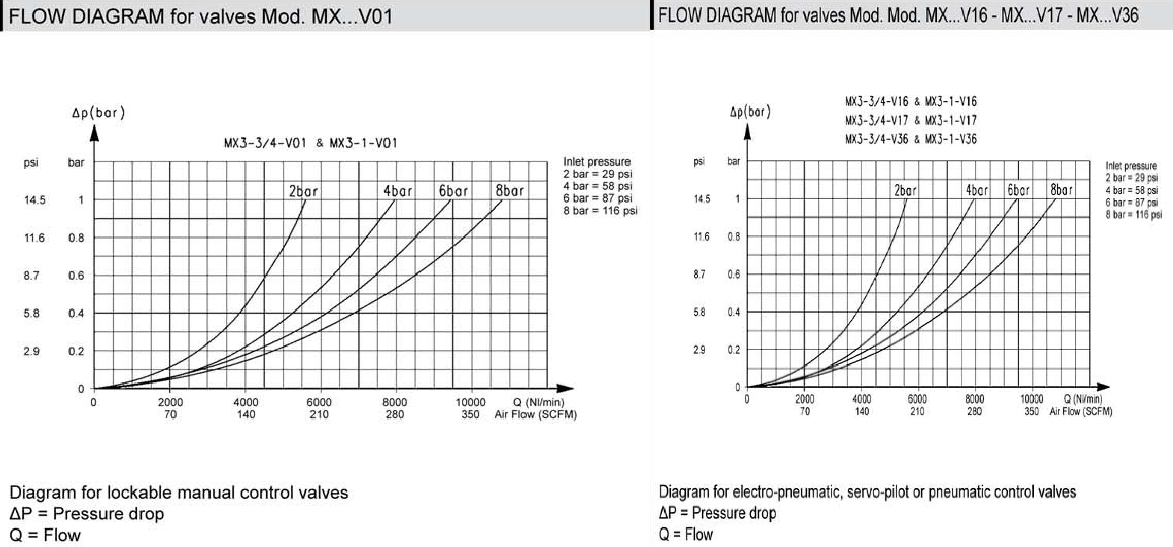
Flow Diagrams
for valves Mod. MX...V01
Diagram for lockable manual control valves
ΔP = Pressure drop
Q = Flow
for valves Mod. Mod. MX...V16 - MX...V17 - MX...V36
Diagram for electro-pneumatic, servo-pilot or pneumatic control valves
ΔP = Pressure drop
Q = Flow
Filters Series MX - Materials
Parts
Materials
1 = Body
Aluminium
2 = Covering
Polyamide
3 = Valve holder plug
Polyamide
4 = Lower spring
Stainless steel
5 = Spool
Stainless steel
Seals
NBR
Technical Specifications
Construction
modular, compact, spool-type
Materials
see TABLE OF MATERIALS
Ports
3/4" - 1" NPTF
Weight
Manual valve = 0,75 kg (1.65 lbs)
Electro-pneumatic valve (V16) = 0,8 kg (1.75 lbs)
Pneumatic valve (V36) = 0,8 kg (1.75 lbs)
Servo-pilot valve (V17) = 0,87 kg (1.9 lbs )
Mounting
in-line,
wall-mounting (by means of clamps),
panel mounting, manual only
Operating temperature
-5°C - 50°C at 16 bar (with the dew point of the fluid),
(23°F - 122°F @ 232 psi, up to 140°F MAX at 145 psi)
50°C - 60°C at 10 bar (with the dew point of the fluid)
Operating pressure
2 - 10 bar (in the pneumatic version - 0,8 - 10 bar) , (30 - 145 psi; 26 in Hg - 145 psi w/ air-piloted
versions)
is the Exclusive Importer of HUMMEL products. We offer over 6,000 different Types and Sizes of RoHS Compliant Liquid Tight Strain Relief Fittings, Cord Grips, Cable Glands, Circular Connectors, Conduit System, Industrial Enclosures and Other Related Cable Management Products which are rated the best in the industry.
7374 S. Eagle Street
Centennial, CO 80112-4221 USA
Toll Free: 800-456-9012 / 303-699-1135 FAX: 303-680-5344